Menu
Menu

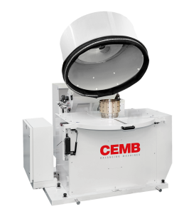
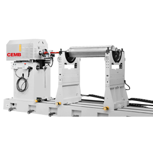
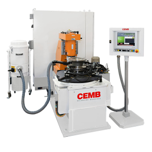
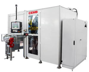
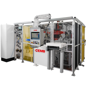
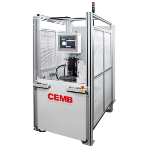
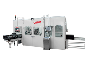
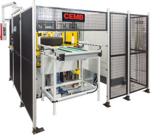
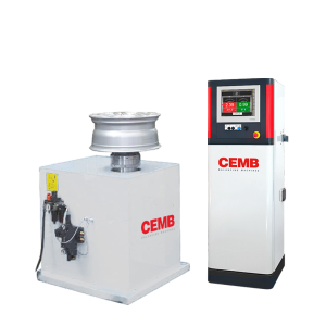
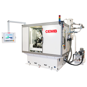
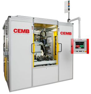
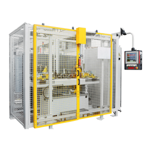
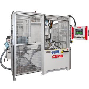
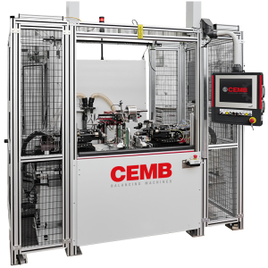
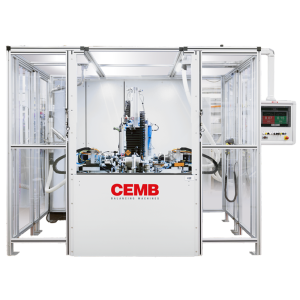
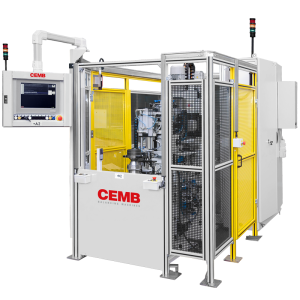
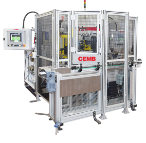
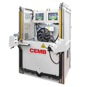
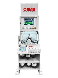
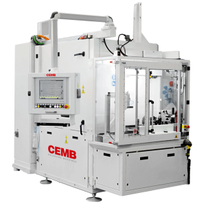
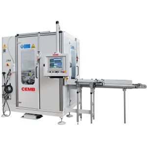
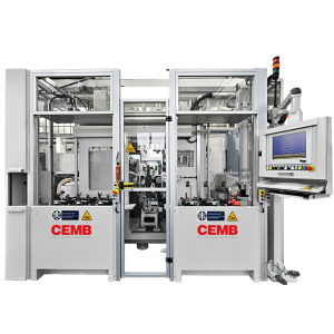
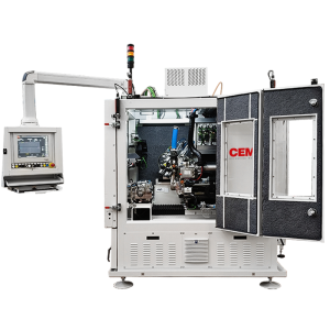
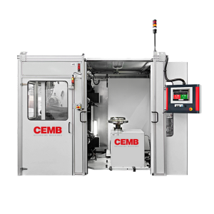
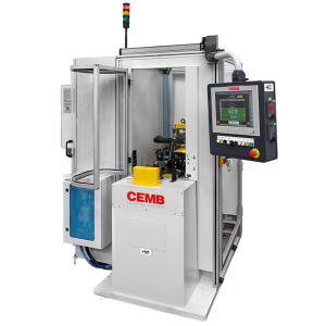
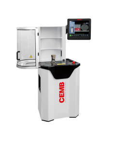
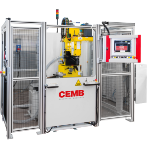
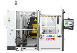
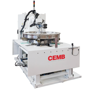
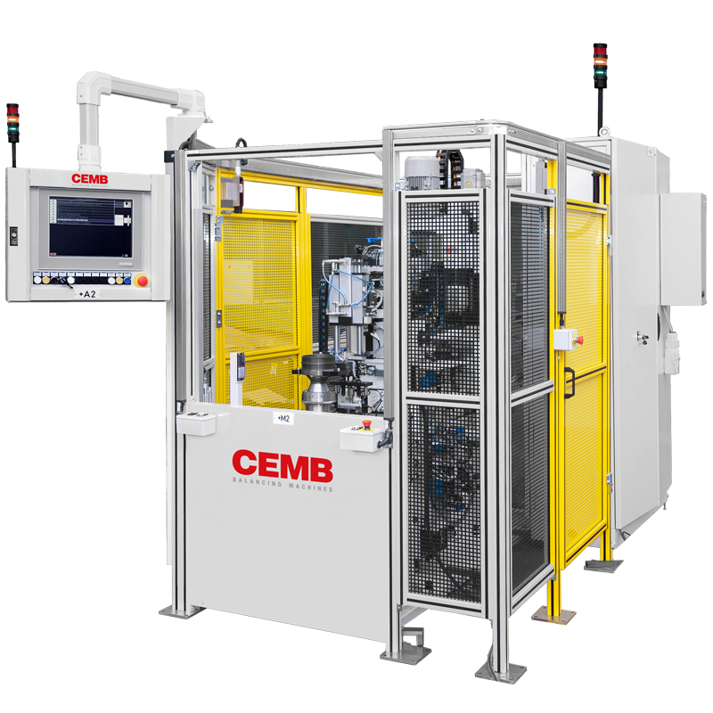
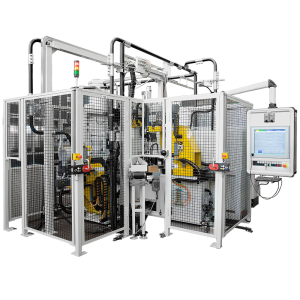
Two-station balancer for flywheels and pulleys

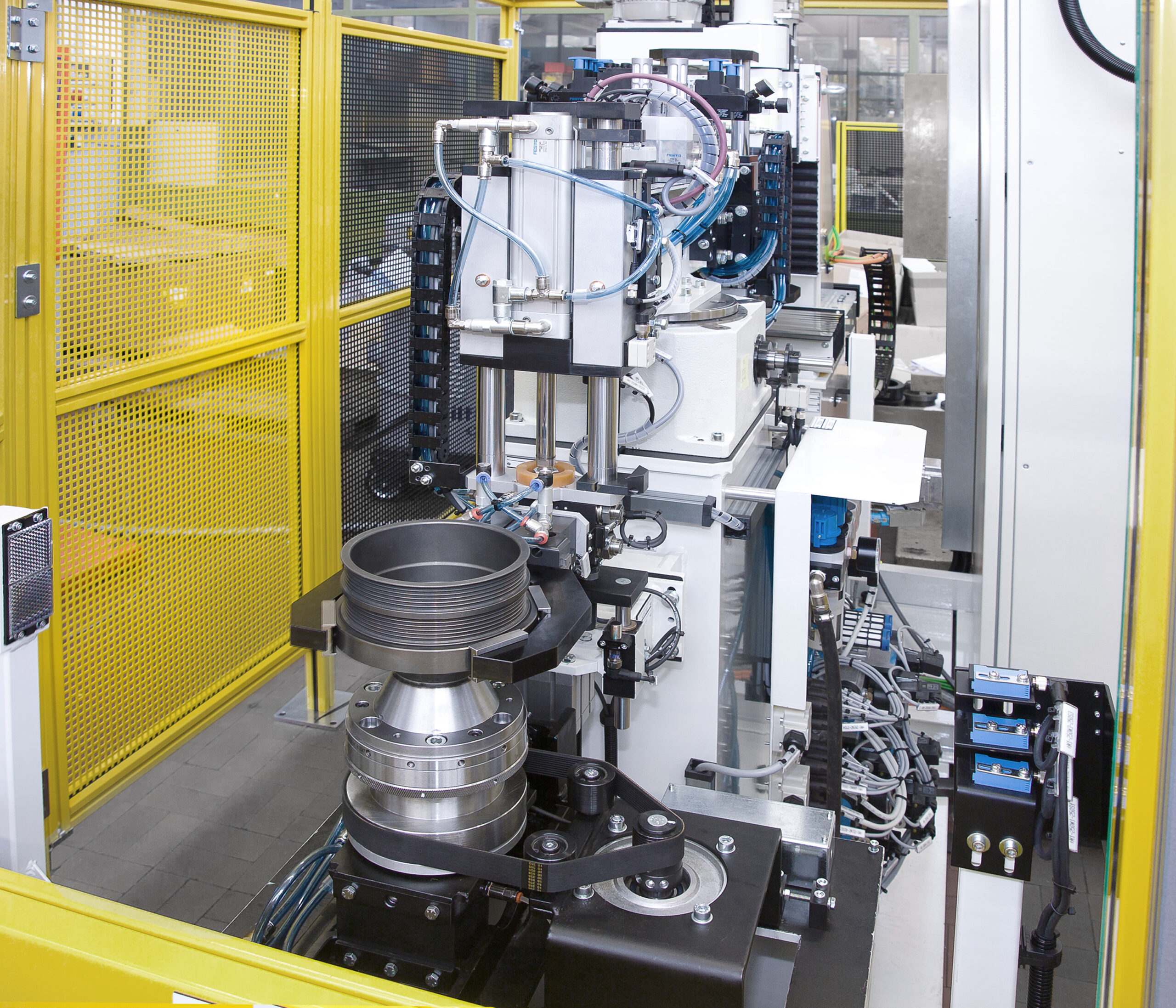
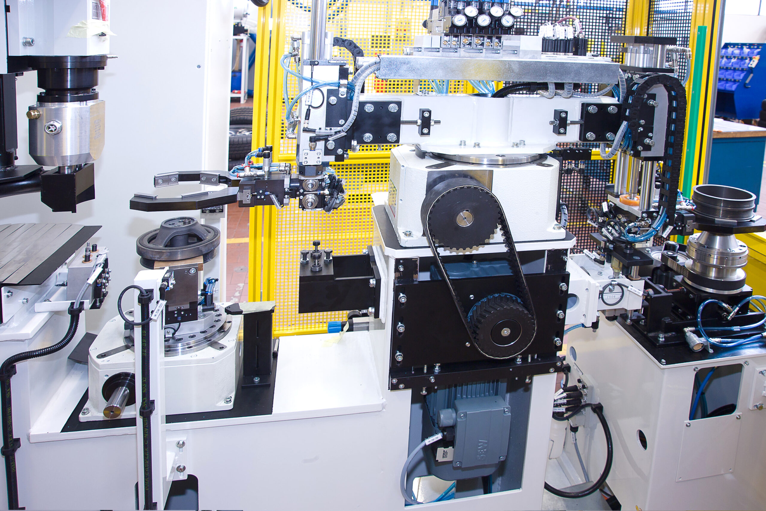
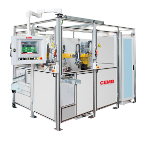
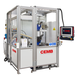
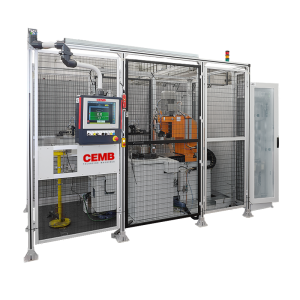
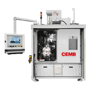
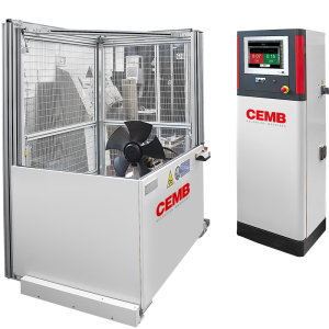
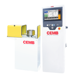
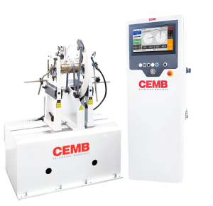
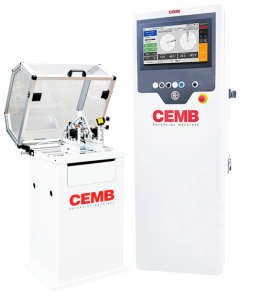
CEMB’s automatic balancer for flywheels and pulleys up to 100 kg ensures maximum performance with two separate stations, reducing cycle times.

Features

  • Ideal for high-volume production of flywheels and pulleys up to 100 kg with high precision.
  • Maximum performance and reduced cycle times due to separate measuring and correction stations designed for optimal efficiency.
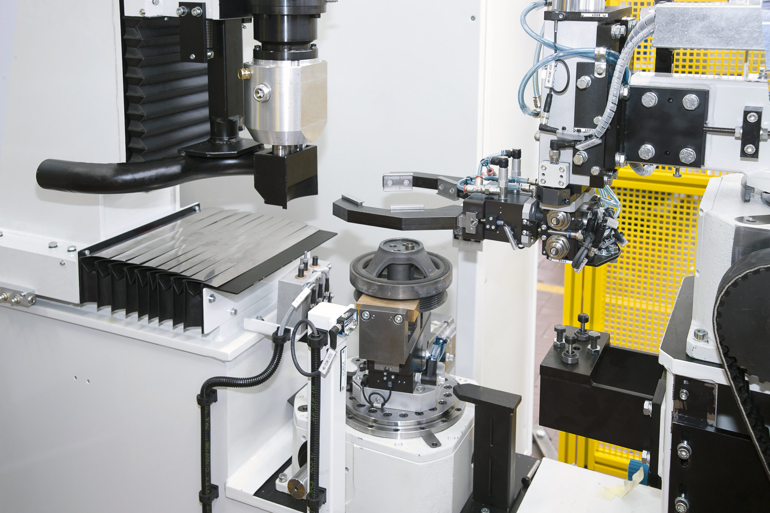
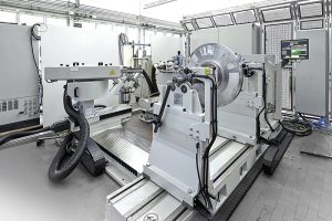
  • Loading system designed to protect the workpiece and ensure the operational accuracy of the machine.
  • Versatile correction by vertical or horizontal drilling to suit different part types and production requirements.
  • Possibility of tilting the workpiece to perform drilling from the opposite side of the clamping plane and with the option of slant drilling.
  • Real-time control and automatic optimization of cutting parameters to maximize tool life.
  • Machine prepared for connection with supervisory and production management systems. It integrates data exchange logic with MES platforms, enabling real-time tracking and monitoring.

Technical data

VUBK5/2ST VUBK50/2ST VUBK100/2ST
Maximum rotor weight (kg) 5 50 100
Maximum rotor diameter (mm) 450 550 750
*possibility of dynamic measurement
Maximum flow rate 5 50 100
Axial drilling VUBK5/UF/2ST VUBK50/UF/2ST VUBK100/UO/2ST
Radial drilling VUBK5/UO/2ST VUBK50/UO/2ST VUBK100/UO/2ST
Axial and radial drilling VUBK5/UF/UO/2ST VUBK50/UF/UO/2ST VUBK100/UF/UO/2ST

Options

Locking tools

Electronic index

Data matrix reader

Tool wear control

Production control with reference piece

Two-spindle head

Laser marking

Micropercussion marking

Scroll to Top

Search by industry

Search by industry

Automotive

Search by industry

Complete wheels and components

Search by rotor

Search by rotor

Complete wheels and components

Search by rotor

Rotating lobes/screws

Request information

    Request information on Impeller – correction by grinding


      Locking tools

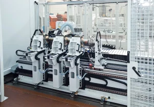
      Automatic clamping systems to mount the part on the balancing machine. These systems ensure perfect centering, easy assembly/disassembly, and safety during the measuring launch.
      Electronic index

      Electronic system that identifies specific rotor reference points to allow correction in specific areas or take into account systematic workpiece imbalance.

      Data matrix reader

      Manual or automatic data matrix code reading system for part traceability.

      Tool wear control

      Automatic tool wear detection system in the case of drilling and milling, which ensures maximum efficiency and safety, avoiding machining with unsuitable tools.

      Production control with reference piece

      Cyclic production control system using part reference, which verifies the quality and repeatability of the production process.

      Two-spindle head

      Unit equipped with two spindles that enables simultaneous drilling, reducing cycle time and increasing productivity.

      Laser marking

      Non-contact device that uses a laser beam to etch the surface of the rotor.

      Micropercussion marking

      Mechanical engraving device that uses a micro-percussion punch to impress a sequence of dots on the surface of the rotor.